I would like to start by mentioning one important point that beekeepers often contact me with: this scale is not intended for permanent loading . The design of the weight cells used means that under constant load they "creep" over time and the weight will show permanent changes of measured values even without changing the weight of the hives. However, this fact does not prevent some manufacturers from selling a scale of identical design as permanently loadable. The scale is designed to measure changes in weight , i.e. I bring the scale to the hive, place it under one of its elevated sides, read the value, note the value and proceed to the next hive. "It takes me about five minutes to 'weigh' eight hives. I repeat the process at any time interval. Personally, I use the weighing most when evaluating the consumption of winter stores. So much for the introduction.
Determining weight gain / loss of hives over time can beekeepers
provide with interesting information about the condition of the colonies. This
information can be used to monitor the progress of nectarflow, or the drawing of supplies, and so on to
optimize the moment of harvesting honey, monitor the progress of feeding and, where appropriate, to prevent crises.
Weighing hives is a problem that is technically professionally solved unfortunately this solution is economically unacceptable for a beekeeper of my type (25 colonies, non-professional, without adjacent fields or regularly hunting forests, in short without a reliable source of nectar). That's why I am
trying to find a way to weigh the hives cheaply and relatively accurately. Maybe
it is time to note that I am not skilled in craftsmanship and that even in
In the field of electrical engineering, I am at the level of a 10-year-old child. Therefore
I was also looking for a solution that is simple in design, in
in all aspects.
I found a simple scale on the internet that is based on lifting the hive on one side and measuring the force required to lift it with a force gauge, either spring or digital. Thus, the absolute weight of the hives is not determined, although it is
it is possible to deduce it. Only the change in the weight of the hive over time is important,
we are basically not interested in the absolute weight of the hive. The advantage of this
The approach is that it allows us to "weigh" all the hives on the apiary, namely
relatively quickly, weighing 10 hives takes about 5 minutes. We are therefore not reliant on a single registration scale that is placed under a single hive, which may behave atypically compared to the rest of the apiary. An example of
such "scale" using a digital force gauge is shown in Fig. 1 , and its function is perhaps clear from the picture. Digital luggage scale can currently be purchased for 100 - 300 CZK.
I made the scale described above. The experience of using it was a little disappointing. The scale has rather poor repeatability. The weight of one hive varied by about 0.5 - 1.5 kg when weighed repeatedly in short succession, and this is quite a lot, considering that we measure about half of the actual weight of the hive in this way. The total error is therefore 1 - 3 kg. For indicative measurements, however, this is sufficient to monitor trends.
By further internet research (google: "hive scale" and later "arduino hive scale") I found that it is possible, and relatively cheap, to make a registration hive scale using so-called strain gauge sensors and a microcomputer that reads and stores the readings from the sensors. Strain gauges are sensors that change the load or pressure in response to a change in electrical voltage, they are found in every digital scale. They can be bought on Chinese servers from about 200 CZK, a microcomputer - e.g. the currently very popular Arduino for about 300 CZK, other small electrical components (e.g. a aplifier to amplify the signals from the sensors) for another 300 - 500 CZK. Total cost I estimate at 1000 - 1500 CZK. The advantage is the determination of the absolute weight of the hive and its progression in time, it allows measuring for example by minutes. Other sensors can be connected to the microcomputer - e.g. temperature, humidity and the measured values can be stored. Data transfer to the Internet, to a mobile phone, etc. is also possible. The disadvantage, however, is the necessary knowledge of electrical engineering and basic programming.
However, I recently found a scale that falls between the above two types in weighing accuracy and design complexity. I found an inexpensive personal scale - namely the Sencor SBS 280 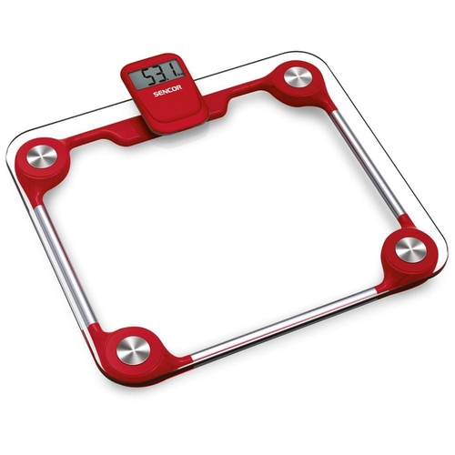 , whose relatively easy adaptation gives a combination of the principle of one-sided hive lifting and strain gauge weight measurement. The scale is currently on sale for a bargain 200 CZK, the other costs I estimate at 0 - 300 CZK, depending on what you find at home, so a total of 200 - 500 CZK .
Compared to other scales of a similar category, this product has one, for
beekeepers essential, advantage. Display
is removable with infrared data transmission . I decided to modify this scale to better suit my beekeeping needs. The goal was to replace the glass loading surface with a more durable metal one, to add another surface as a permanent "floor" to allow the scale to be placed under the hives, to make the scale smaller overall, and to modify the power supply of the weighing unit to (micro)pencil cells. The modification procedure is as follows:
- After removing the scale from its packaging, we check the correct function of the scale so that we don't have to worry about the mess later.
- Te turn the scale over "on its back" and unscrew all the screws we find in the plastic housing, there are 11 of them, 10 of them are visible at a glance, the last one is hidden under the cover of the power cell.
- Once uncovered, we can see the 4 strain gauge sensors located in the corners of the scale. The wiring is stuck with a strip of adhesive tape, we peel this off. We note the position of each strain gauge so that we can position them the same in a future beehive scale. The strain gauges are not screwed on, they are just "clipped on", so we peel them off. See Fig. 2.
- The wiring from the control unit leads to the strain gauges via two metal tubes, these are carefully cut with tin snips. The wiring must not be damaged. The cables should not be cut and e.g. shortened or lengthened. The system should be temperature calibrated to the specific conductors.
- Under each sensor is another screw that connects the glass plate to the plastic body of the scale. Unscrew the screws and separate the glass plate, leaving the aluminium spacers glued on.
- The aluminum spacers can be separated from the glass after heating them with a heat gun. Caution! There is a risk of burns or cuts from the cracked plate, use gloves and safety glasses. The plate will no longer be needed.
- Insulated plastic parts must be cut off. The cuts are indicated by blue lines in the Fig. 2. . After point 7 we should be at the stage shown in the Fig. 3.
- Prepare the new "floor" of the scale, on which the scale will be permanently attached. Here the imagination is no longer limited. I have chosen a wooden board, 30 x 15 x 2 cm.
- Screw the aluminium spacers back into the original plastic corners of the scale and then screw them to the board. I chose the same geometry as in the original scale (square), but you can arrange the strain gauges in a line, side by side, as you need anyway.
- "Snap" the strain gauges back into the plastic corners and arrange the wiring. Wrap the wiring with electrician's tape and, if necessary, attach it with plastic holders to the plate, these can be bought at electrical supply stores. See Fig. 4.
- Solder the wires to the contacts for the power cell, to which we will later connect the (micro)pencil cell power supply, marked with blue rings in Fig. 4.
- In the plastic part that covers the control unit we drill a hole through which we will later thread the wiring to the strain gauges. If I were doing this a second time, I would take better measurements. This way I have another hole in the control unit cover for ventilation :-). You have to be very careful when working with the wiring, the wires tend to pull out of the factory soldered connections.
- Thread the wiring (to the strain gauges through the drilled hole and the power cable through the hole created when the control unit cover was cut off), screw the cover together.
- Screw the cover of the control unit to the board with two screws, hiding them in the holes made after cutting.
- At the other end of the power cables, attach the plastic holder for 2 (micro)pencil batteries. It can be bought in electrical goods for about 10 CZK.
- It remains to solve the surface on which the bottom of the hive will sit. In the described arrangement, a metal sheet, 2 mm thick, 15 x 15 cm, curved at the edges, can be used. But it is possible to improvise in any way. Wood, thicker plywood, etc. can be used. Drill 4 holes in the loading surface where the strain gauges will sit. This will make it easier to position the loading surface in relation to the strain gauges and, once glued, will result in a stronger joint. Glue the surface to the scale, e.g. with silicone.
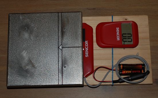
- Draw guide lines on the loading surface. These must be measured so that the hive touches the loading surface as far as possible midway between all the strain gauges, so that the weight of the hive is evenly distributed on them - see testing the scales below. The position of the lines depends on the type of bottom of the hive, its design.The final product can be seen in Fig. 5.
Testing the scale
tested the scale in terms of the dependence of the measured value on the position of the balance under the hive, in terms of the repeatability of the measurement and in terms of the dependence on the air temperature.
During the testing, it turned out that the position of the scale under the hive is a key parameter that affects the accuracy of the weighing. The scale was placed in extreme front, back, left and right positions under the hive. The measured values showed a variance of up to 3.3 kg (specifically 18.2 kg - 21.5 kg). Therefore, to ensure good repeatability of the measurements, it proved necessary to ensure that the scale was always placed in the same position under the hive. For this reason, I made arrows on all the bottoms of the measured hives (in the middle of the bottom, on the side under which I placed the weight). I drew guide lines on the scale so that the scale would be inserted equally deep under the hive, and a further arrow to indicate the centre of the scale. So in the final step, I insert the scale under the hive so that the arrowheads (on the bottom of the hive and on the scale) are opposite each other (see Fig. 6, Fig. 7).
As far as the repeatability of the measurements is concerned, I have weighed one hive a total of 12 times, and I have always obtained an identical value (in this particular case 18.8 kg). The variance was therefore 0.0 kg. . The scale was always placed in the same position relative to the hive.
for the temperature dependence of the hive weight measurement, I made a total of 7 measurements in temperatures from -3.9 °C to 13.0 °C, the scale was placed permanently outside, it was at ambient temperature, I positioned a dumbbell with a declared weight of 12 kg on it. The variance of the measured values was a maximum of 0.3 kg, namely from 11.9 kg to 12.2 kg. Moreover, the measured values showed no correlation with temperature..
I would be grateful for any comments and feedback or questions...write to nezadal@seznam.cz